Swageless Cable Extremity
The Groxx GRXHLLC Horizontal Lifeline system for concrete substrates is a professional-grade fall-arrest solution that converts rigid reinforced concrete into a dynamic safety anchorage. The system is specifically engineered to manage high-velocity kinetic energy while maintaining the structural integrity of the slab.
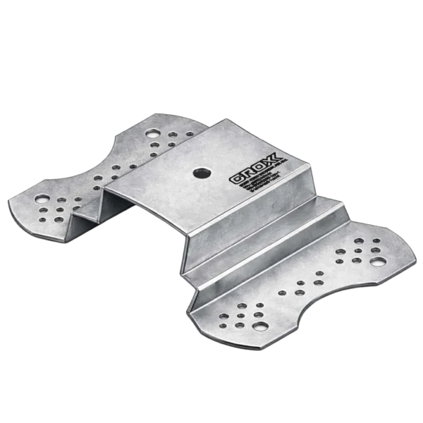
The reliability of the GRXHLLC system begins with the interface between the G-Anchor Extremity Posts and the concrete slab.
Substrate Requirement: Installation is typically performed on reinforced concrete with a minimum compressive strength of 25 MPa (C20/25).
Fixing Mechanism: Utilizing GRX851 Modified Epoxy Resin and GRXNG143 SS316 Threaded Bolts.
The “Bond” Logic: Unlike mechanical expansion anchors that rely on friction and induce internal “bursting” stresses (limiting edge distance), the GRX851 chemical anchor creates a tension-free molecular bond. The epoxy penetrates the concrete pores, distributing the load across the entire surface area of the drilled hole (10d–15d depth). This allows for maximum pull-out resistance even in cracked concrete zones.
Concrete is a high-modulus, non-yielding material. In a fall event, the system must prevent the “impact spike” from reaching the user or the anchors.
Stage 1: Inline Energy Absorption: The system incorporates a high-capacity 316 Stainless Steel Energy Absorber. Upon reaching a pre-defined trigger force, the absorber undergoes controlled deformation (unfolding), which extends the deceleration distance and caps the Maximum Arrest Force (MAF) to safe levels (typically <6kN).
Stage 2: Cable Span Deflection: The 8mm 7×19 wire rope acts as a flexible spring. The horizontal tension and the “sag” (deflection) during a fall absorb a significant portion of the energy before it reaches the extremity G-Anchors.
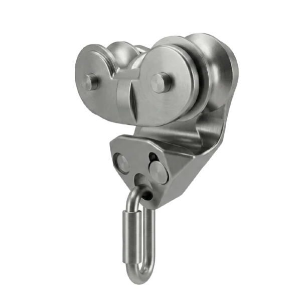
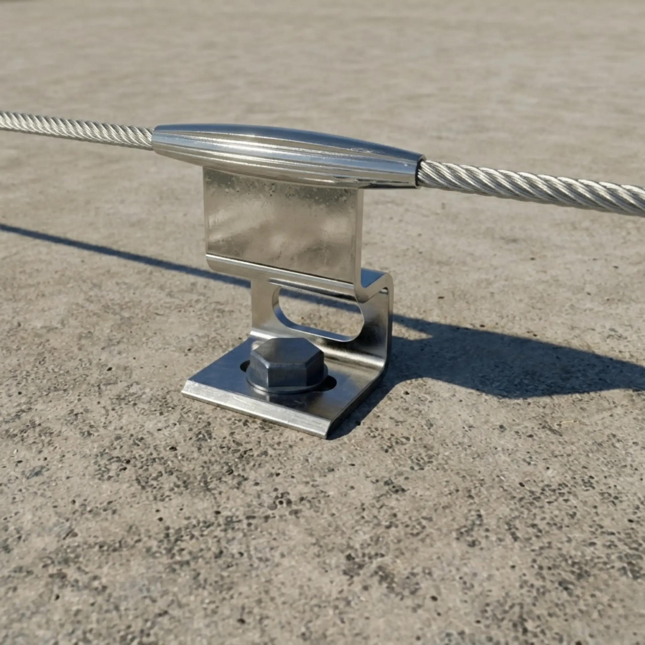
Continuous protection is maintained through the engineering of the Intermediate Supports and the Traveler Shuttle.
Continuous Tie-Off: The traveler shuttle features a unique “gated” geometry. As the user moves along the slab, the shuttle passes over intermediate supports without manual disconnection.
Bypass Geometry: The intermediate supports hold the cable in a way that leaves the top and bottom of the cable profile accessible to the shuttle’s tracking wheels/jaws, ensuring 100% connectivity across the entire length of the slab.
The GRXHLLC system is engineered and tested to meet the following safety benchmarks:
EN 795:2012 Type C: European standard for anchor devices using flexible anchor lines.
CEN/TS 16415:2013: Multi-user testing requirements, certifying the system for use by multiple workers simultaneously (refer to specific system layout for user limits).
ISO 9227: High-level salt spray testing for corrosion resistance, ensuring longevity in coastal concrete installations.